


Stay Informed
Follow us on social media accounts to stay up to date with REHVA actualities
|
|
|
|
|
Nhat Nguyen | Martin Kremer | Hendrik Fuhrmann | Philipp Ostmannand | Dirk Müller |
RWTH Aachen University, E.ON Energy Research Center, Institute for Energy Efficient Buildings and Indoor Climate, Aachen, Germanynhat.nguyen@eonerc.rwth-aachen.de | ||||
Among the various pollutants, fine and coarse particulate matter are major risks to human health. They can penetrate deeply into the respiratory tract and increase mortality and morbidity even at low concentrations [2]. Previous studies on wet scrubbers regarding particle removal mainly focus on different approaches to improve the removal efficiency of particulate matter, especially fine particles [3]–[8]. These modified wet scrubber concepts can remove even submicron particles with an efficiency of up to 99 % [5]. However, the studies do not consider the energy demand required to remove the particulate matter. With increasing particle removal efficiencies, the need for energy-efficient methods has grown.
In this study, we investigate a wet scrubber concept with low pressure drop at the air side and low pressurization of the water leading to reduced operational energy demand. We replace the common spray injection of water droplets with a perforated plate. The droplets are fed into the airflow by dripping through the perforated plate. Furthermore, the generated droplets in this wet scrubber feature a bigger diameter than droplets generated by spray injection. Hence, a droplet separator for bigger droplets with less pressure drop can be used to remove excess water droplets from the air vent [9].
To analyze the removal efficiency and pressure drop of this wet scrubber concept we develop a test bench. Figure 1 shows the developed wet scrubber test bench and the positions of the utilized sensors. The air duct features a 300 mm x 300 mm cross-section, which tapers into a 130 mm diameter pipe at the end. A HEPA filter at the air duct inlet removes ambient particulate matter in the supply air. An aerosol generator feeds the particles into the airflow (Particle Feed). The particle feed’s nozzle is positioned in the center of six horizontal cylinders (35 mm) that are staggered vertically. This cylinder arrangement introduces additional turbulence and facilitates a homogenous particle distribution within the air duct. A calming section of 1000 mm between the wet scrubber section and cylinders enables particle mixing into the airflow and a homogenous flow structure. At the end of the wet scrubber section, a honeycomb structure with a depth of 80 mm and at an angle of 13° to the vent acts as a droplet separator. Another honeycomb structure with a depth of 40 mm directly downstream of the first one acts as a flow straightener. The honeycomb structures in this study have a diameter of 9 mm. A second HEPA filter downstream of the wet scrubber section protects the fan from the remaining particulate matter in the airflow. An external air conditioning system provides conditioned air to the test bench.
We use the differential pressure measurement Δps to monitor the pressure in the duct and to adjust it in the case of overpressure. The pressure within the duct has a significant effect on the droplet shape due to the low pressures used to generate the droplets in this wet scrubber concept. We use the differential pressure sensor Δpf to monitor the clogging of the first HEPA filter. Although we measure the water temperature in this study, we do not control it. An optical particle spectrometer (OPS) measures the particle sizes and particle size distribution. The measurable particle sizes range from 0.3 µm to 10 µm. A 9 mm probe in the center of the air duct is installed 470 mm downstream of the wet scrubber area (OPS). It is oriented parallel to the flow direction and guides the collected particles through a 90° elbow tube into the OPS. An external vacuum pump is connected to the probe to ensure isokinetic sampling. A venturi throttle in accordance with DIN 51678‑1 measures the airflow rate V̇a. The fan of the test bench uses this measurement to adjust its fan speed according to the external air supply settings. The programmable logic controller monitors the sensor values and adjusts the water and airflow rates. It measures the sensor data every 10 ms and averages the values.
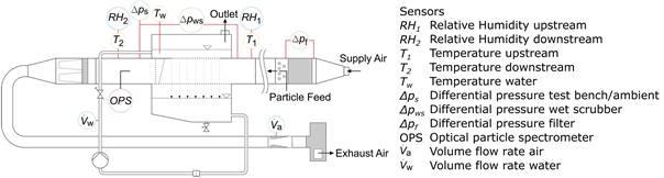
Figure 1. Schematic diagram of test bench with sensors.
The wet scrubber section consists of a water basin on top of the air duct, a perforated plate, a collection tank below the air duct, honeycomb structures, a pipe system, and a pump. Figure 2 shows the perforated plate that separates the water basin from the air duct. The plate has a thickness of 1 mm and a porosity of 1.3 %. Another horizontal honeycomb structure between the air duct and the collection tank prevents falling drops from bouncing back into the air duct after impinging on the water surface. A pipe system connects the water basin and the collection tank. It contains a pump, a line regulating valve, and a filter. The pump controls the water mass flow. The line regulating valve supports pump control at part load operation. The filter has a 0.6 mm mesh and protects the pump from coarse particulate matter. The water basin has an outlet at the top to prevent overpressure.
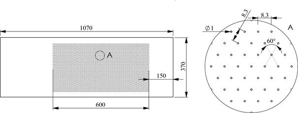
Figure 2. Perforated plate, dimensions in mm.
During this study’s experiments, the airflow rate is kept constant at 560 m³/h. The aerosol mass flow rate is also kept constant throughout all experiments at 1.11 g/h. To evaluate the performance of the wet scrubber we define the particle removal efficiency η as the relative difference in particle counts between consecutive test runs because the particle count is only measured downstream of the wet scrubber:
| (1) |
where Kwet and Kdryare the particle numbers per cubic meter with an active and an inactive wet scrubber, respectively. The particle removal efficiency and the pressure drop are investigated for three different scenarios, which differ in temperature and humidity. Table 1 sums up the boundary conditions for each scenario.
Table 1. Boundary conditions of investigated scenarios.
Scenario | Temperature [°C] | Rel. Humidity [%] |
Summer | 32 | 30 |
Transition | 13 | 55 |
Winter | 3 | 72 |
An experiment to determine the particle removal efficiency consists of two phases. In the first phase, the particle concentration is measured with an inactive wet scrubber. In the second phase, the measurement is performed under the same boundary conditions with an active wet scrubber. In each phase, the particle concentrations are measured for five minutes. These concentrations are used to calculate the particle removal efficiency. The OPS uses scattered light to determine the optical diameters of the particles. It divides the particle into 17 bins. From now on, unless otherwise noted, the diameter will always refer to the optical diameter. The OPS cannot size particles with a diameter greater than 10 µm and assigns them to bin 17. For each of the investigated cases, ten experiments are performed. The measurements are averaged in each case and the uncertainty of the measurement is determined according to the JCGM [11].
Table 2 shows the mean pressure drop of the investigated wet scrubber over the water flow rate for all studied scenarios. The pressure drop increases with higher water flow rates. Depending on the water flow rate, the pressure drops range from 3.92 Pa to 6.58 Pa. The difference in pressure drops increases with rising water flow rates.
Table 2. Mean pressure drop for all investigated scenarios.
Volume flow rate in m³/h | 0 | 2 | 4 | 6 |
Mean pressure drop in Pa | 3.92 | 4.47 | 5.22 | 6.58 |
Figure 3 displays the particle removal efficiency over the mean particle diameter for the transition scenario at the three investigated water flow rates. The particle removal efficiency for particles smaller than 3.58 µm is negative. This indicates that the particle count in the measurements with an active wet scrubber is higher than in the measurements with an inactive wet scrubber. Particles larger than 5.82 µm have positive particle removal efficiencies. The positive particle removal efficiencies increase with rising water flow rates and larger particle sizes. The efficiency rises to 29 % for the largest particle sizes at the highest water flow rate. The uncertainty bars indicate a very good repeatability of the measurements at small particle diameters. The uncertainty increases with increasing particle size to ±3 percentage points (pp). The negative particle removal efficiencies range from −1.2 % to −3 % with an uncertainty of approximately ±0.23 to ±0.36 pp. The particle removal efficiencies observed in the summer and winter scenarios behave similarly to the particle removal efficiencies in the transition period.
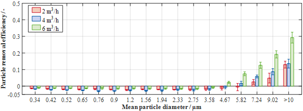
Figure 3. Particle removal efficiency over mean particle diameter for different water flow rates in the transition scenario.
Figure 4 shows the particle removal efficiency for the various scenarios at a water flow rate of 4 m³/h. In contrast to the other two scenarios, the particle removal efficiencies in the winter scenario at 3.58 µm and 4.67 µm are positive. The particle removal efficiency is positive in all scenarios for particles larger than 5.82 µm in diameter. At very small and large particle sizes the particle removal efficiency of every scenario is within the same range considering the measurement uncertainties. At 4 m³/h, the highest particle removal efficiency of 14 % is observed for particles larger than 10 µm with winter boundary conditions.
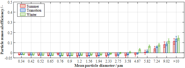
Figure 4. Particle removal efficiency over mean particle diameter for all scenarios at a water flow rate of 4 m³/h.
The pressure drop across the investigated wet scrubber is 1 – 2 orders of magnitudes less than in already existing wet scrubbers. This wet scrubber concept achieves a particle removal efficiency of up to 38 % depending on water flow rate and particle size. However, the particle removal efficiency of the investigated wet scrubber is significantly lower than for existing wet scrubbers due to the relatively low number of droplets in this concept. The water is not atomized due to the low pressures applied. Therefore, the droplet sizes for the investigated concept are larger than those for existing wet scrubber concepts. Hence, the investigated wet scrubber concept has a smaller water surface area as it produces fewer droplets and droplets with larger diameters. This results in a lower particle removal efficiency because particle removal via interception is less likely with less contact area between the water and the particles. The generated droplets are also significantly larger than the hole diameter of the perforated plate because of water accumulation at the plate underside. At a water flow rate of 6 m³/h, the water forms ligaments through the plate holes without wetting the plate surface. These ligaments break into small droplets due to the relative velocity between the airflow and the water. The increase in particle removal efficiency at higher water flow rates is a result of the increased water surface area due to an increase in the number of droplets. The negative particle removal efficiencies may indicate an agglomeration of particles outside of the measurable range. However, the current OPS does not enable further investigation of particles smaller than 0.3 µm in diameter due to technical limitations. Furthermore, the OPS detected an insignificant number of particles in experiments with an active wet scrubber and an inactive particle feed. Hence, small water droplets that passed the droplet separator are not the cause of the significant increase in measured particles in the active wet scrubber measurements. Overall, the particle removal efficiency is approximately the same for the investigated boundary conditions. Therefore, temperature and humidity appear to have little influence on the particle removal efficiency. On the other hand, the particle removal efficiency increases with higher water flow rates.
We have developed a test bench to investigate a new wet scrubber concept. This wet scrubber concept reduces the energy demand due to low pressure drops and water pressurization. The experimental results show that the particle removal efficiency for coarse particles increases with higher water flow rates. A plate with a shorter perforated section may result in better droplet generation because the hydrostatic pressure is higher for the same water flow rate. Hence, the length of the perforated section shall be investigated in future studies. There is no particle removal detected for fine particles. However, if particle agglomeration occurs and increases particle sizes to larger diameters, this wet scrubber concept can be used as a pre-filter to another method that removes fine particles.
Further investigations could also address the adhesion of water to the plate surface. The adjustment of the adhesion between the plate surface and droplet can result in better dripping behaviour and smaller droplets, which increase the water surface area. An increased water surface area facilitates the particle removal efficiency for fine and coarse particles. The adhesion can be influenced by altering the roughness of the plate surface or by applying a waterproof coating to the plate surface. Wet scrubbers can remove both particulate and gaseous pollutants. Therefore, the removal of gaseous pollutants needs to be investigated in future studies to facilitate a holistic evaluation of this wet scrubber concept.
We gratefully acknowledge the financial support by the Federal Ministry for Economic Affairs and Climate Action (BMWK), promotional reference 03ET1606B.
[1] Nguyen, N., Kremer, M., Fuhrmann, H., Ostmann, P. and Müller, D. (2023). Experimental study of an innovative wet scrubber concept in regards to particle filtration and pressure loss.43rd AIVC - 11th TightVent - 9th venticool Conference.
[2] World Health Organization (2016). Ambient air pollution: a global assessment of exposure and burden of disease. World Health Organization.
[3] Biswas, S., Rajmohan, B. and Meikap, B.C. (2008). Hydrodynamics characterization of a counter-current spray column for particulate scrubbing from flue gases.Asia-Pacific Journal of Chemical Engineering, 3(5), 544–549.
[4] Raj Mohan, B. and Meikap, B.C. (2009). Performance characteristics of the particulate removal in a novel spray-cum-bubble column scrubber.Chemical Engineering Research and Design, 87(1), 109–118.
[5] Zhao, H. and Zheng, C.G. (2008). Modeling of Gravitational Wet Scrubbers with Electrostatic Enhancement.Chemical Engineering & Technology, 31(12), 1824–1837.
[6] Lee, B.-K., Mohan, B.R., Byeon, S.-H., Lim, K.-S. and Hong, E.-P. (2013). Evaluating the performance of a turbulent wet scrubber for scrubbing particulate matter.Journal of the Air & Waste Management Association (1995), 63(5), 499–506.
[7] Hu, S., Gao, Y., Feng, G., Hu, F., Liu, C. and Li, J. (2021). Experimental study of the dust-removal performance of a wet scrubber.International Journal of Coal Science & Technology, 8(2), 228–239.
[8] Qian, J., Wang, J., Liu, H. and Xu, H. (2022). Numerical Investigation of Fine Particulate Matter Aggregation and Removal by Water Spray Using Swirling Gas Flow.International journal of environmental research and public health, 19(23).
[9] Bürkholz, A. and Muschelknautz, E. (1972). Tropfenabscheider. Übersicht zum Stande des Wissens.Chemie Ingenieur Technik - CIT, 44(8), 503–509.
[10] Clanet, C. and Lascheras, J.C. (1999). Transition from dripping to jetting.Journal of Fluid Mechanics, 383, 307–326.
[11] JCGM (2008). Evaluation of measurement data - Guide to the expression of uncertainty in measurement.
Follow us on social media accounts to stay up to date with REHVA actualities
0