


Stay Informed
Follow us on social media accounts to stay up to date with REHVA actualities
|
|
|
Kevin VerniersR&D Digital Innovation, Renson Ventilation NV, Waregem, Belgiumkevin.verniers@renson.be | Frederik LosfeldR&D Digital Innovation, Renson Ventilation NV, Waregem, Belgium | Ivan PolletR&D Digital Innovation, Renson Ventilation NV, Waregem, Belgium |
Traditional demand controlled ventilation systems are based on constant pressure control in a specific duct position to indirectly alter the airflow rate of the fan(s) in the air handling unit [1]. Unfortunately, this approach does not adequately benefit the energy efficiency of a ventilation system when the demand changes in one or more rooms. For this reason, an optimized fan control strategy taking into account the damper position of each room was proposed [1,2,3].
This optimized control strategy considers the duct with the highest pressure losses for a given demand at a given moment as the critical path and fully opens the damper on this critical path to minimize the maximal operating pressure and in that way the fan consumption. As a consequence, the system pressure is variable and determined by the pressure loss of the critical path. This optimized control strategy is indicated here as critical path control, whereas the constant pressure approach is non-critical path control.
The impact of both control approaches on mean operating pressure and auxiliary fan consumption of demand controlled mechanical extract ventilation (DC-MEV) is discussed in this article by means of multizone simulations.
The studied DC-MEV system is the Healthbox 3.0 (HB3). Air is naturally supplied into the habitable rooms via window vents, while demand controlled mechanical extraction takes place in the functional rooms (bathroom, toilet, …). In addition, demand controlled mechanical extraction points can be provided in the habitable rooms to improve the indoor air quality or thermal comfort. This extended configuration is indicated as Smartzone (SZ) and comprises of seven ducts, whereas the initial configuration is referred to as non-Smartzone (non-SZ) containing four ducts. The multizone simulations treated both HB3 configurations each once equipped with critical and non-critical path control.
Table 1lists the parameters utilized in the multizone simulations. A single detached house was considered that was equipped with either a SZ or non-SZ HB3, an open or closed kitchen, and an airtightness level (v50) of 0.6; 3; or 6 m³/(h.m²). This resulted in six houses and for each was a total of 100 simulations with four variable parameters (occupancy, orientation, …) conducted. Each simulation encompassed the heating season.
Figure 1shows the flow of one simulation as means of an example. The first step generates mechanical extraction ventilation rates over the heating season for a random house configuration. The second step creates conductance values (C values) describing the entire ductwork as well as the air inlets. Thus, the C values represent the system characteristic and are based on field big data. The third step utilizes the extraction rates over the heating season and both the system and fan characteristic to calculate the operating fan pressures during the heating season for the case of critical as well as non-critical path control. The fan characteristics were measured in laboratory. The fourth step derives the fan power (and consumption) over the heating season by means of the earlier obtained fan pressure operating points. For each heating season, the average of the fan operating pressure, power, and consumption are determined.
Table 1. Considerations for the multizone simulations.
Parameter | Description |
Dwelling | · 1 detached house with open or closed kitchen and 3 airtightness levels (v50): 0.6; 3; 6 m³/(h.m²) · Heating season: 1st of October up to 15th of April · Per configuration: set of 100 simulations with 4 variable parameters: occupancy, terrain roughness, dwelling orientation and day start type · 2*3 times 100 or a total of 600 possible house configurations |
Ventilation system | · Healthbox 3.0 without (4 ducts) and with Smartzone (7 ducts) |
Ductwork down and upstream | · Generation of multiple (up to 1000) ductwork configurations including air inlets, C values derived from field big data, checked with lab measurements on components at the nominal airflow rate |
Fan operating airflow rate (m³/h) | · Average airflow rate per simulation over the heating season · Moving average over set of simulation up to convergency |
Fan operating pressure (Pa) | · Average pressure per simulation over the heating season · Moving average over set of simulation up to convergency |
Fan power (W) | · Average fan power per simulation over the heating season · Moving average over set of simulation up to convergency |
Fan consumption (kWh) | · Average fan consumption per simulation over the heating season · Moving average over set of simulation up to convergency |
Reduction factor f | · Ratio of average fan consumption in case of critical path to non-critical path control |
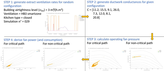
Figure 1. Flow of a single simulation. This example is simulation n° 29 out of 100 for the house configuration consisting of a closed kitchen, a building airtightness level of 3 m³/(h.m²), and a HB3 Smartzone ventilation system.
Figure 2is subdivided into four cases where the dwellings consisted of either an open or closed kitchen while being equipped with either a non-SZ or a SZ HB3 configuration. The ventilation system was once performed with critical path control on the one hand and non-critical path control on the other hand. The result for each case represents the average of the fan operating pressure and airflow rate for each simulation over the heating season.
For all cases, as expected, critical path control provides the lowest operating pressure in contrast to non-critical path control. The observation originates from the fact that non-critical path control generally has no entirely opened damper as opposed to critical path control. The maximal average operating pressure for non-critical path control rises up to about 350 Pa, except for the non-SZ with a closed kitchen where the highest value is around 300 Pa. Non-SZ has less ducts as there are less rooms to extract polluted air from, consequently there is less chance of a duct exhibiting high pressure losses. Additionally, a closed kitchen has a lower required minimum ventilation rate compared with an open kitchen according to the Belgian regulations (difference of 25 m³/h). These items explain why non-SZ with closed kitchen exhibits only a maximal average operating pressure of 300 Pa, while SZ with open kitchen achieves most frequently the value of 350 Pa compared to the remaining cases.350 Pa is the maximum achievable operating pressure of the fan according to its characteristics that were measured in laboratory and utilized in the simulations. In Belgium, there are no requirements regarding the operating pressure, the recommendation is to keep it as low as possible for energy and acoustic reasons.Similar conclusions are drawn from the minimal average operating pressures during non-critical path control. The explanations from non-critical path control apply also for critical path control that obtains a clearly lower minimal and maximal average operating pressure.
For all cases, the average airflow rate varied from 40 to 100 m³/h which is mostly less than one third of the installed nominal extraction capacity of the ventilation unit. For a similar exposure to CO2, the deployment of non-SZ results in a higher airflow rate compared to SZ, although the occurrence of these higher airflow rates is rather limited. The difference is caused by smaller local minimal airflow rates (10% instead of 30%, Belgian regulations) and window vents designed at 10 Pa instead of 2 Pa for the SZ system.

Figure 2. Average operating pressure (Pa) in function of the average airflow rate (m³/h) for four cases (closed/open kitchen and Smartzone/non-Smartzone). Ventilation system based on critical or non-critical path control. Dashed lines represent the ventilator curves at different voltages.
The result for each case in Figure 3 represents the average fan consumption as a function of the outlet duct conductance obtained for each simulation over the heating season. Similar to Figure 2, for each case are the lowest fan consumption values of at most 50 kWh obtained when critical path control is deployed. Critical path control reduces the fan consumption by about 50 to 75%.
The absolute difference in fan consumption between critical and non-critical path control becomes smaller when the conductance of the outlet duct increases. This is due to the fact that for a high conductance of the outlet duct, the additional pressure over the inlet ducts has less impact on the total pressure, and thus on the fan consumption. To conclude, critical path control shows the highest saving potential for outlet ducts with a low conductance or a high resistance.
Figure 3 shows also that non-critical path control exhibits a slightly lower average fan consumption in a dwelling containing a closed kitchen when compared with a dwelling having an open kitchen due to lower average operating pressures, while there is no difference when critical path control is applied.
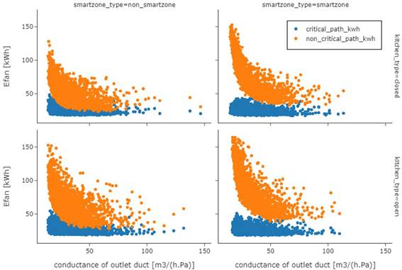
Figure 3. Average fan consumption (kWh) as a function of the outlet duct conductance (m³/(h.Pa)) for four cases (closed/open kitchen and Smartzone/non-Smartzone). Ventilation system based on critical or non-critical path control.
For each simulation was a reduction factor (f) calculated based on the average fan consumption of critical path control relative to that of non-critical path control. The result for the considered cases is depicted inFigure 4. Each boxplot demonstrates quite some difference amongst the obtained reduction factors. The median value varies between about 30 % and 50 %. According toFigure 4, the largest reduction in fan consumption is obtained when a SZ ventilation system is deployed in a dwelling containing an open kitchen. In this case, the median value of the reduction factor equals about 33 % which is lower than the median values of the other boxplots. The median value of the reduction factor increases to 44 % in case of a dwelling composed of an open kitchen while being equipped with non-SZ ventilation system. Therefore, it can be concluded that adopting a SZ ventilation system with critical path control instead of non-critical path control leads to the highest reduction in energy consumption when compared to a non-SZ ventilation system. This higher reduction is related to the higher number of extract ducts in case of the SZ system.
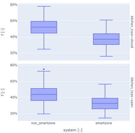
Figure 4. Boxplots of reduction factors obtained for four cases (closed/open kitchen and Smartzone/non-Smartzone). Reduction factor = average fan consumption critical path control divided by average fan consumption non-critical path control.
The impact of critical versus non-critical path control on the mean operating pressure and auxiliary fan consumption for residential DC-MEV systems was examined by means of multizone simulations during the heating season. The results demonstrated that critical path control leads to the lowest operating pressure over the duct work while also obtaining the lowest auxiliary fan consumption. The smartzone DC-MEV exhibits a higher operating pressure than non-smartzone due to the higher amount of ducts present in the system. The fan power consumption reduction factor based on critical path control relative to non-critical path control indicates that a house with open kitchen that is equipped with smartzone DC-MEV achieved a value of 33 % in contrast to the 44 % for non-smartzone DC-MEV.
This research has received no external funding.
[1] Mysen M., Woollett J. (2015) Commissioning for energy—optimal demand controlled ventilation. REVHA European HVAC Journal, vol. 52, no. 2, pp. 20–24.
[2] Truninger K. (2013). VAV system with genuinely demand-controlled fans. REHVA European HVAC Journal, vol. 50, no. 4, pp. 15–18.
[3] Mysen M., Schild P. G. (2011). Requirements for well functioning Demand Controlled Ventilation. REHVA European HVAC Journal, vol. 48, no. 5, pp. 14–19.
Follow us on social media accounts to stay up to date with REHVA actualities
0