

Stay Informed
Follow us on social media accounts to stay up to date with REHVA actualities
|
|
Martina Mudrá * | Ján Takács * |
martina.mudra@stuba.sk | jan.takacs@stuba.sk |
* Department of Building Services, Faculty of Civil Engineering, Slovak University of Technology in Bratislava, Slovakia | |
The non-renewable nature of fossil fuels, climate change, and the consequences of human activity that result in rising levels of atmospheric CO₂ concentration force society to consider using alternative or renewable energy sources [2]. One way to decarbonise the heat supply in buildings by using environmentally friendly and high-energy-efficiency equipment and technologies that save primary energy is through existing district heating and cooling systems that supply several buildings at once [6]. The European Directives on the energy performance of buildings and on energy efficiency promote high-efficiency alternative systems, such as:
a) decentralized energy supply systems using energy from renewable energy sources,
b) combined heat and power generation – cogeneration,
c) district heating or cooling, especially if it uses energy from renewable energy sources in full or in part,
d) use of environmental energy by means of heat pumps, as far as it is technically, functionally and economically feasible [3, 4, 5].
Combined heat and power through a cogeneration unit and heat pumps will be designed for the West housing estate located in the town of Brezno, Slovakia. The existing hot water boiler plant is situated near the Hron River. The proximity of a watercourse creates preconditions for an excess of groundwater in the surrounding subsoil – a source of low-temperature energy. This energy will be transformed to a higher temperature level by water-to-water heat pumps [1]. The district boiler plant is a source of heating water and domestic hot water for 782 flats, ice arena, restaurant and a retirement home [7, 8].
During heating season, there is uninterrupted 24-hour operation. In summer, the boiler plant is in operation from 4:00 am to 11:00 pm, i.e. 19 hours. The heat transfer medium is hot water with the original design temperature gradient of 90/70°C. The heat source is represented by three hot water boilers with a total output of 6.76 MW [1]. Figure 1shows the interior view of the existing boiler plant.
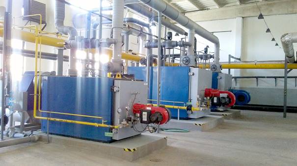
Figure 1. Interior view of the existing three hot water boilers [1]
Hourly consumption of natural gas in m³ was provided by the heat source operator for the period of 2016–2018. Figure 2 logically shows that the largest consumption of natural gas was in the heating season and the lowest in the summer season. The natural gas consumption also depends on the climatic conditions in a given period [1]. By multiplying the values of natural gas consumption by the calorific value of the fuel, the total amount of heat contained in the natural gas was obtained.
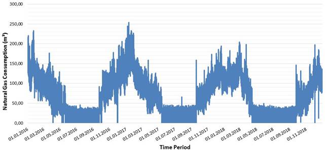
Figure 2. Natural gas consumption in m³ over 2016 – 2018. [1]
A cogeneration unit and heat pumps shall be installed instead of the existing heat source – hot water boilers. The energy source for driving the cogeneration unit will be natural gas. The energy source for driving the heat pumps will be the electricity produced by the cogeneration unit. The cogeneration unit and heat pumps will be used to prepare hot water in an accumulative way. The storage tank will be located behind the cogeneration unit and heat pumps and, at a time when the demand for hot water consumption is reduced, the heated hot water will accumulate in it. The accumulated heat will be supplied to the grid at the time of increased demand. The essence of the design is ensuring a continuous operation of the equipment so that it works as long as possible and with a minimum of starts [1].
To determine the optimal heat output of the device, we need to know the domestic hot water consumption over 24 hours. The heat output of the device can be determined based on the average hourly heat demand for domestic hot water preparation in June. Working days – Monday, Wednesday will be compared with a free day – Saturday. Figure 3 shows that the domestic hot water is supplied between 4:00 am and 11:00 pm, i.e. 19 hours. On weekdays, the hot water consumption is highest in the morning and evening. On weekends, the hot water consumption is increased compared to working days and it is on average the same throughout the day [1].
The average hourly heat demand for domestic hot water preparation in 2016 was 275 kW, in 2017 it was 280 kW, and in 2018 it was 267 kW. By comparing the data for the period 2016 – 2018, the heat output of the cogeneration unit and two heat pumps was set to 270 kW [1].
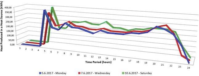
Figure 3. Hourly heat demand for domestic hot water preparation over 24 hours on 3 June 2017 [1]
The cogeneration unit and heat pumps will be located in front of the boilers in the direction of the return heating water flow. The heat transfer medium – heating water has a temperature of 45°C. The aim is to produce a heat-transfer working substance – heating water with a temperature of 60°C. The temperature drop in the hot water system is therefore 60/45°C, which means that the temperature difference (Dq) is 15 K. The volume flow at a heat output of 270 kW and a temperature difference of 15 K is 15.48 m³/h. The heat pumps operate with a primary gradient of 5/1°C – this means that a low-temperature heat source enters the heat pumps (groundwater from wells) and is transformed in the heat pumps to a higher temperature, transferred to the secondary heating system circuit. Return heating water with a temperature of 45°C enters the heat pump and is heated up by 10 K, which means that the water temperature at the outlet of the heat pump will be 55°C. This time the temperature difference (Dq) is known to be 10 K and the volume flow (M) through both heat pumps is 15.48 m³/h.
Figure 4 shows the schematic diagram of the cogeneration unit and heat pumps in the district heating system.

Figure 4. Schematic diagram of cogeneration unit and heat pumps (HE – heat exchanger, HP – heat pump, CU – cogeneration unit, ST – storage tank). [1]
The output of both heat pumps was calculated to be 180 kW. It follows from the above that the heat output of the cogeneration unit will be 90 kW. The cogeneration unit works with a temperature gradient (Dq) of 20 K as standard. This means that if water with a temperature of 55°C enters the cogeneration unit, the cogeneration unit will heat the water to 75°C at the outlet of the cogeneration unit. We know determine the volume flow rate that the cogeneration unit must take to reach 60°C at the outlet of the unit and before entering the hot water storage tank. The volume flow through the cogeneration unit to reach 60°C at the outlet of the unit and before entering the hot water storage tank is 3.87 m³/h. For better controllability of the system, two identical two-stage water-water heat pumps are proposed. The advantage of a two-stage heat pump is that it has two output stages and can therefore be operated on a single compressor with half the output. Because the heat transfer medium cools the primary heat transfer medium – the pumped water, it could freeze and form icing on the heat pump evaporator, which would be destroyed after a certain time. Therefore, a separation heat exchanger was used in the primary circuit to ensure an intermediate circuit with antifreeze between the pumped groundwater and the heat pump. Through a detailed recalculation, the design of two identical heat pumps was determined, while the heat output of one was 89.6 kW. For the cogeneration unit together with the heat pumps to create a set, it is necessary to harmonize their thermal outputs and also electrical inputs, as the cogeneration unit will supply electricity to the heat pumps. The interaction between the heat pumps and the cogeneration unit was simulated using calculation programs in cooperation with the supplier of these devices. From the three simulations performed, the most solution was selected, which set the heat output of the cogeneration unit at 90 kW [1].
During the operation of the cogeneration unit and heat pumps during the heating season, all the heat energy produced by these devices is used to prepare domestic hot water and to heat the heating water. In summer, when the produced thermal energy is consumed only for the preparation of heat, there may be an excess of heat produced. These surpluses must be stored in a hot water storage tank, from which they are tapped during peak periods in the event of greater heat demand. If this excess energy does not accumulate but flows into the system, the temperature of the return heating water entering the heat pumps can gradually increase, leading to overheating of the heat pumps that may reach complete shutdown. The volume of the storage tank was determined to be 10,000 litres by detailed calculations [1].
The reason to apply the cogeneration unit and heat pumps in the given operation was the fact that district heating systems have the potential for high-efficiency combined heat and power generation and efficient use of environmental energy through heat pumps. These devices can be installed separately, but as mentioned in the article, there is also a presumption of the interaction of both devices.
The cogeneration unit could also supply electricity to the public electricity network, but at the time of this optimization study, there was a ban on connecting new larger sources of electricity to the public electricity network.
The application of a cogeneration unit and heat pumps to the existing operation of hot water gas boilers saves fossil fuel – natural gas, the reserves of which are gradually running out. The energy of the environment – groundwater – is used instead. From an energy point of view, the same or more heat energy is produced but less fuel is consumed. As far as the economy is concerned, saving fuel also saves money that would otherwise be spent on buying it. Electricity is produced through a cogeneration unit and there is no need to supply electricity to the installations from the public grid, except in cases where there is a failure or maintenance of the cogeneration unit. They also evaluate the annual sales for combined heat and power generation positively.
To ensure energy efficiency, the original technologies are gradually being replaced by modern equipment. A cogeneration unit and heat pumps were used to produce the heat needed to prepare hot water in an accumulative way, especially in the summer. During the heating season, the additional heat produced will not accumulate but will be supplied to the heating network.
The application of a cogeneration unit and heat pumps to the existing operation of hot water gas boilers saves fossil fuel – natural gas, the reserves of which are gradually running out. The energy of the environment – groundwater – is used instead. From an energy point of view, the same or more heat energy is produced but less fuel is consumed. As far as the economy is concerned, saving fuel also saves money that would otherwise be spent on buying it. Electricity is produced through a cogeneration unit and there is no need to supply electricity to the installations from the public grid, except in cases where there is a failure or maintenance of the cogeneration unit.
Only through the application of renewable energy sources and combined production of electricity and heat in district heating systems will Slovakia manage to meet its targets by 2030. These include reduction of greenhouse gas emissions by 20% and increasing the share of energy from renewable energy sources in gross final energy consumption by 19.2% [6].
This work was supported by the Ministry of Education, Science, Research and Sport of the Slovak Republic through the grants VEGA 1/0304/21, VEGA 1/0303/21 and KEGA 005STU-4/2021.
[1] MUDRA, M. Streamlining the operation of heat source TP5 for the housing estate Západ in Brezno [diploma thesis]. Bratislava: Slovak University of Technology in Bratislava, Faculty of Civil Engineering, Department of Building Services, 2019. 106 p.
[2] PETRÁŠ, D. - LULKOVIČOVÁ, O. - TAKÁCS, J. - FÜRI, B. Renewable energy sources for low temperature systems. Bratislava: Jaga Group, 2009. 223 p. ISBN 978-80- 8076-075-5.
[3] Directive 2010//31/EU of the European Parliament and of the Council of 19 May 201O on the energy performance of buildings.
[4] Directive 2012/27/EU of the European Parliament and of the Council of 25 October 2012 on energy efficiency.
[5] Directive (EU) 2018/844 of the European Parliament and of the Council of 30 May 2018 amending Directive 2010/31/EU on the energy performance of buildings and Directive 2012/27/EU on energy efficiency.
[6] Integrated National Energy and Climate Plan 2021 – 2030. Ministry of Economy of the Slovak Republic. Bratislava. October 2019. From: https://www.mhsr.sk/uploads/files/zsrwR58V.pdf (online)
[7] https://www.veolia.sk/pre-zakaznikov/mesta-obce/centralne-zasobovanie-teplom (online)
[8] https://vesr.sk/sk/veolia-energia-brezno (on line)
Follow us on social media accounts to stay up to date with REHVA actualities
0